
Blog


Designing and Analyzing a Stellar Interferometer with FRED Software
In:
Stellar interferometry is a powerful technique used in astronomy to achieve high angular resolution measurements of celestial objects, including stars and galaxies. With FRED software, designing and analyzing a classic Michelson stellar interferometer becomes a structured and insightful process. This blog post walks you through the steps of creating and simulating a Michelson stellar interferometer using FRED.
Introduction to Stellar Interferometry
Astronomical interferometers have been instrumental in groundbreaking discoveries, from measuring the diameters of stars to identifying exoplanets. The Michelson stellar interferometer, first proposed in the late 19th century, has played a pivotal role in these advancements. The following guide uses FRED to replicate a Michelson interferometer, highlighting key design and analysis techniques.
Designing the Stellar Interferometer
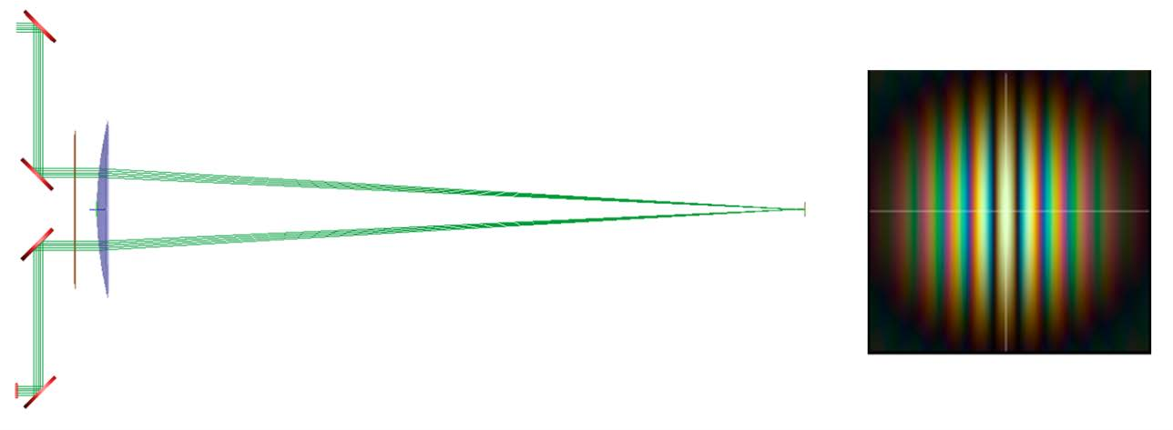
The Michelson interferometer design consists of four mirrors, two pinholes, a positive lens, and a detector. The system's geometry is depicted in Figure 1 below.

Figure 1: Geometry of the Michelson stellar interferometer.
In this setup, starlight enters the interferometer and is split into two paths (P1 and P2) by the mirrors. The light then passes through a set of pinholes in an opaque mask before being focused by a plano-convex lens onto a detector. The interferometer's ability to measure stellar diameters depends on the optical path difference (OPD) between these two paths, which varies with the angular diameter of the star being observed.
Analyzing Interference Patterns
The interference pattern on the detector is crucial for determining the angular extent of the observed star. Figure 2 illustrates the white-light interference patterns produced by a star with an angular extent of 1 arcsecond. By adjusting the mirror separation, we can observe how the visibility of the interference fringes changes.

Figure 2: Left: Interference pattern with a 50 mm mirror separation. Right: Reduced visibility with a 100 mm mirror separation.
As the mirror separation increases, the fringe visibility decreases, providing insights into the angular diameter of the light source. This phenomenon is crucial for accurately measuring stellar diameters.
Implementing Global Variables and Scripts in FRED
To simulate the interferometer in FRED, a script with global variables is used. This script allows you to adjust key parameters such as mirror separation, pinhole radius, and light source characteristics without manually editing the script. Figure 3 shows the global script variables used in this simulation.

Figure 3: Global variables in the FRED script for simulating the Michelson interferometer.
The script generates coherent plane wave sources representing the star, performs a coherent ray trace, and calculates the interference pattern at the detector. By scanning the mirror separation, the script can determine fringe visibility and, consequently, the angular extent of the star.
Conclusion
FRED software’s ability to simulate complex optical systems like the Michelson stellar interferometer makes it an invaluable tool for astronomers and optical engineers. By accurately modeling the interference patterns and adjusting system parameters, users can gain deeper insights into stellar measurements and refine their optical designs.
__________________________________________________________________________________________________________________________________________________________________________________
This blog post was created based on the information provided by Photon Engineering, a partner of CBS Europe.
Download the PDF: FRED Application Note - Stellar Interferometer