
Blog


Display Systems with FRED
In:
Created:
30 Jul 2024
Introduction
Display systems are intricate assemblies composed of various optical components, with the light source being paramount. Effective display systems utilize mechanisms to direct light through or off text or graphics for optimal information display. To achieve precise light control, optical apparatuses manage the angular and positional output. FREDsoftware significantly reduces the time and cost of prototyping these systems by 30-50% compared to traditional methods.
Sources
FRED is adept at simulating a wide range of light sources commonly found in display systems. These include LEDs, RGB LEDs, incandescent lamps, HID, Neon, ARC, and fluorescent sources. The software supports CAD imports in IGES and STEP formats, enabling the modeling of complex geometries. Additionally, FRED can handle single or multiple grids of rays with specific position and angular apodizations, surface modeling with user-defined emission models, and measured data models, such as Radiant Imaging Source™ Models.

Figure 1: Examples of light sources and fixtures modeled in FRED.
System Geometry
Creating system geometry in FRED is straightforward with its intuitive graphical interface. Users can also import geometries from IGES or STEP CAD formats and optical design programs or convert from ASAP output text files. FRED offers extensive options for creating surfaces, including standard planes, conics, cylinders, ellipsoids, hyperboloids, toroids, polynomial surfaces, Zernike, Nurb, Meshed, revolved curves, extruded curves, composite curves, splines, and user-defined surfaces.

Figure 2: Various methods for modeling display geometry in FRED, including imported CAD models, revolved curves, and arrayed assemblies.
The software's multiple document user interface allows for cutting, copying, and pasting components between documents. Entities can be logically arranged into hierarchies, such as assemblies and subassemblies, which correspond to the physical layout of the system. Surfaces can be trimmed by any implicit surface or an aperture collection curve.
FRED excels at importing IGES and STEP files, easily handling planes, conics, meshes, NURBs, Bezier surfaces, and even higher-order surfaces, like a fifth-order signal reflector.

Figure 3: A signal reflector modeled using a fifth-order surface and imported CAD geometry.
Optical Apparatus to Control Light Output
Display systems often require mechanisms to control light output in angular and positional spaces, such as grooves, dots, surface roughness, paint, or prismatic films. FRED can model these control structures effectively, leveraging its versatile array function to handle repetitive structures.

Figure 4: Repeated features in a PDA backlight generated using an array of surface structures.
Creating grooves and curves and then extruding or revolving these structures to form Fresnel and prismatic features is simple in FRED, ensuring precise light propagation.


Figure 5: Faceted display structure modeled as a 1D array of extruded curves. Raytracing light from the source through the display verifies the operation of these prismatic reflectors.
Sample Display Applications
Lightpipes
Lightpipes, which channel light from one or multiple sources to one or several destinations, are often made of plastic and may suffer from light leakage due to molding issues. FRED excels in visualizing and modeling these optical devices, whether directly in the program or through CAD import. The software can model LED and incandescent sources illuminating the lightpipes and trace the sources through the lightpipe to analyze irradiance and spot position on any surface.
Figure 6: Lightpipe models created in FRED. Geometry can be imported from a CAD model or generated directly using a coil element or extruded curve.
The program can also analyze the uniformity of illumination and model sources, including bitmaps or letters, to evaluate throughput and uniformity issues.

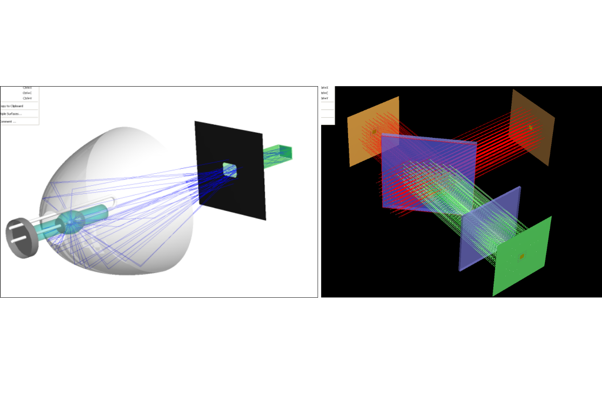
Figure 7: Spot diagram and irradiance plot for a curved lightpipe illuminated by three colored LEDs.
Color image analysis can reveal common issues in RGB LED designs, such as color uniformity problems.

Figure 8: Color image and irradiance plot for a curved lightpipe illuminated by three colored LEDs.

Figure 9: Intensity plot for a curved lightpipe illuminated by three colored LEDs.
LED Illumination – Color Image Capability
Each wavelength in FRED has an associated weight and color, and the software includes tools for setting wavelength sequences and weights, such as photopic and scotopic spectral responses. This capability is ideal for systems requiring colorimetry calculations.

Figure 10: Methods for evaluating spectral content from colored LEDs.
Conclusion
FRED software is a powerful tool for designing and prototyping display systems, offering comprehensive features for modeling light sources, system geometry, and optical apparatuses. Its capabilities significantly enhance the efficiency and accuracy of developing advanced display technologies.
__________________________________________________________________________________________________________________________________________________________________________________
This blog post was created based on the information provided by Photon Engineering, a partner of CBS Europe.