
Blog


Advanced Polarization Modeling Techniques with FRED Software
In:
FRED software offers robust capabilities to simulate the polarization of light through optical systems, supporting components like birefringent wave plates and polarizers. This blog post explores three examples of polarization modeling using FRED: absorptive dichroic and wiregrid polarizers, a calcite half-wave plate, and the Maltese cross phenomenon.
Example 1: Polarizers
Consider a simple polarizer system with randomly-polarized rays passing through an x-polarizer to a detector.

Figure 1: Randomly polarized light filtered through an x-polarizer and collected by a detector.
Two methods can be used to model a polarizer in FRED. The simpler method involves adding a polarizer coating to a surface. In the FRED document, create a new coating under "Polarizer/Waveplate Coating (Jones Matrix)" and select "X Linear Polarizer."
A more accurate method involves modeling absorption-based polarization in a custom material. Create a new material under "Sampled Birefringent and/or Optically Active Material," and set differing real and imaginary refractive index components.


Figure 2: Polarization Spot Diagram before (left) and after (right) the x-polarizer. Only x-polarized components propagate through the polarizer.
Example 2: Wave Plates
Wave plates shift one polarization component of light with respect to another, transforming its polarization state. Quarter-wave plates change linear to circular polarization and vice versa, while half-wave plates change x-polarized light into y-polarized light.

Figure 3: X-polarized light passing through a +45° ½ wave plate transforms into y-polarized light.
The simplest method to model a wave plate is by assigning a ½ wave plate coating to a surface. For a more accurate approach, assign a custom birefringent material to a rod element. Set properties such as wavelength and refractive indices based on materials like calcite.

Figure 4: Polarization Spot Diagram after x-polarized light passes through a calcite ½ wave plate.
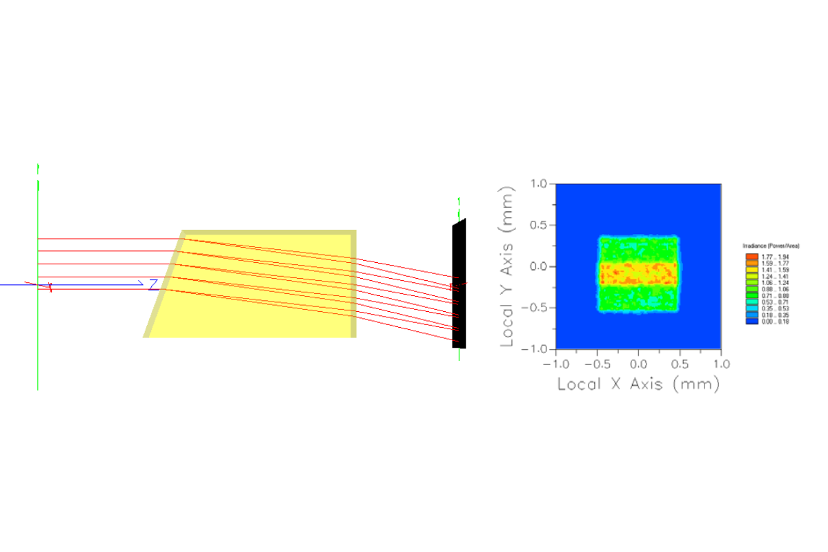
Example 3: Maltese Cross Phenomenon
The Maltese cross is an interference figure formed by birefringent materials placed between crossed linear polarizers. This phenomenon is useful for identifying birefringent specimens.

Figure 5: Maltese cross system setup (left) and irradiance pattern on the detector (right).
Conclusion
Polarization plays a crucial role in many optical systems, from LCDs to microscopes. FRED software provides powerful tools to model and analyze polarization effects, enhancing the design and optimization of complex optical systems.
___________________________________________________________________________________________________________________________________________________________________________________
This blog post was created based on the information provided by Photon Engineering, a partner of CBS Europe.