Blog


Bessel Beam Generation Using an Axicon
Bessel Beam Generation Using an Axicon
Introduction
Bessel beams are a unique form of light propagation that resists diffraction. The light distribution of a Bessel beam remains tightly focused with high irradiance over long distances. Additionally, Bessel beams are self-healing, meaning the light pattern will regenerate after partial obstruction. These properties make Bessel beams valuable for optical trapping and tweezing, high-precision drilling, and communication applications.
Description of a Bessel Beam
Bessel beams are light fields described by a Bessel function of the first kind. The cross-section of a Bessel beam consists of concentric rings, each containing the same infinitesimal amount of energy, including the central lobe.

Figure 1. Irradiance pattern along the cross-section of a Bessel beam. The Bessel function is shown in the upper right.
Higher-order Bessel beams are altered along the azimuthal direction according to the equation \( J_l(k_rr) \exp(i l \phi) \), where \( k_r \) determines ring spacing and \( l \) determines azimuthal phase variation. In the far-field, the Bessel beam forms an annular ring.
Generating a Bessel Beam with an Axicon
Creating an ideal Bessel beam is practically impossible because it would require an infinite number of rings over an infinite extent. However, pseudo-Bessel beams, confined to an aperture, can be generated. The simplest way to produce a Bessel beam is with an axicon—a cone-shaped refractive material or reflective surface that converts an incident plane wave into a self-interfering light cone, creating concentric fringes.
Creating an Axicon in FRED
To create an axicon in FRED, follow these steps:
1. Create a “circular cone” element with Simple Glass material, Transmit coating, and Allow All raytrace control. Set a base semi-aperture of 1 mm and a height of 0.1 mm.
2. Generate a Simplified Optical Source of the type Collimated Source (plane wave) and enable the Coherent option to ensure self-interference. Set the source wavelength to 500 nm.
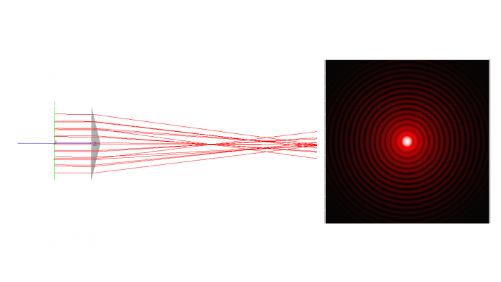
3. Position an absorbing surface with an attached analysis surface 12 mm from the axicon.

Figure 2. Left: a collimated plane wave illumination passes through a glass axicon. Right: further along the axis, a detector is placed in a region of self-interference where a pseudo-Bessel beam is generated.
Observing the Bessel Beam
To observe the Bessel beam in FRED:
1. Click Analysis → Coherent Scalar Wave Field to display a graph of irradiance.
2. To view the light field, right-click the graph and select Show Field Amplitude. In a 0.2 mm diameter observation region, distinct Bessel rings will be visible.


Figure 3. Distribution of irradiance (left) and light field (right) in the self-interfering region beyond an axicon illuminated by a plane wave with a wavelength of 500 nm.
FRED effectively models Bessel beam behavior by simulating the creation of pseudo-Bessel beams using coherent illumination and standard optical components such as axicons, lenses, and annular slits. This capability makes FRED a valuable tool for researchers and engineers developing applications that leverage the unique properties of Bessel beams.
___________________________________________________________________________________________________________________________________________________________________________________
This blog post was created based on the information provided by Photon Engineering, a partner of CBS Europe.

