
Blog


Optimizing Mobile Displays: The Edge-Lit LED Screen with Diffuser
In:
Created:
31 Jul 2024
Introduction
In the world of mobile devices—smartphones, e-readers, and smartwatches—optimal performance hinges on precise optical engineering. A key aspect of this engineering is the display, which must deliver uniform illumination across its surface and a wide range of viewing angles while maintaining high optical efficiency to minimize power consumption and extend battery life. Edge-lit LED screens, utilizing compact and efficient LED lights coupled with a transparent waveguide, are an excellent solution. Various elements, including reflective back surfaces, microstructure patterns, brightness-enhancing films, and diffusers, enhance these displays' efficiency and uniformity. This blog post explores a FRED model that demonstrates the effectiveness of an edge-lit LED smartphone display using a gradient diffuser for uniform illumination.
Edge-Lit LED Screen with Diffuser
Setting Up the Model
Waveguide
The primary component is a rectangular waveguide with dimensions of 25 x 40 x 1 mm (semi-width, semi-height, and semi-depth). This waveguide is the foundation upon which the other elements are built. The waveguide block's material, coating, and raytrace control properties are essential for optimizing light transmission and guiding.

Figure 1. Waveguide block material, coating, and raytrace control properties.
LED Array
An LED array is embedded within the waveguide's edge to maximize optical efficiency. The LED is modeled as a small rectangular Lambertian emitter, positioned just inside the top face of the waveguide block. The array consists of five identical LEDs spaced 10 mm apart along the top face of the waveguide.
To set this up, create a New Detailed Optical Source. Under the Source tab, select Standard Glass as the Immersion Material. Position the LED just inside the Top Face of the waveguide block under the Location/Orientation tab. The LED's ray positions and directions are set to random within specified dimensions and angular ranges, ensuring a Lambertian angular distribution type.

Figure 2. LED array settings.
Reflectors
Reflective surfaces are essential for enhancing the display's optical efficiency. A back-reflector, positioned just behind the waveguide, recycles light that would otherwise exit the display's backside. Additionally, a small front-reflector is placed in front of the embedded LEDs to reduce excess light refraction and improve uniformity. The back-reflector's dimensions are [25 x 39 mm] and the front-reflector's are [25 x 1 mm].

Figure 3. Display geometry, including LED array (central LED shown in yellow), front-reflector (red), and back-reflector (green).
Diffuser with Scripted Scatter
A diffuser gradually scatters light trapped within the waveguide, ensuring uniform illumination. To counteract the decreasing irradiance gradient from the LEDs, a tailored scatter function is used. This scatter function, modeled with an exponential equation, ensures maximum scatter at the waveguide's end, achieving uniform illumination.
Create a new scatter function by selecting Scatterers → Create a New Scatterer, and choose "Scripted" from the drop-down menu. The scatter probability, p, is defined by the exponential function:
p=a⋅Exp(b⋅(−g_Ypos+40))−1
where the parameters a=4a = 4a=4 and b=0.04b = 0.04b=0.04 are constants. The scatter occurs only for rays with y-positions sufficiently above the LED array (y > 25 mm from the bottom). Assign this custom scatter script to one side of the waveguide.

Figure 4. Assign the scripted scatter function (“Tailored Scatter” in this case) to the front or back of the waveguide under the Scatter tab of the surface.
Raytrace Control
To enhance simulation efficiency, a Monte Carlo raytrace control is applied to the scattering surface. This control prevents ray splitting at each scattering event, making the simulation more efficient.

Figure 5. New Raytrace Control: Select “Monte-Carlo” as the Parent Ray Specifier to prevent ray splitting at scattering events.
Evaluating the Display
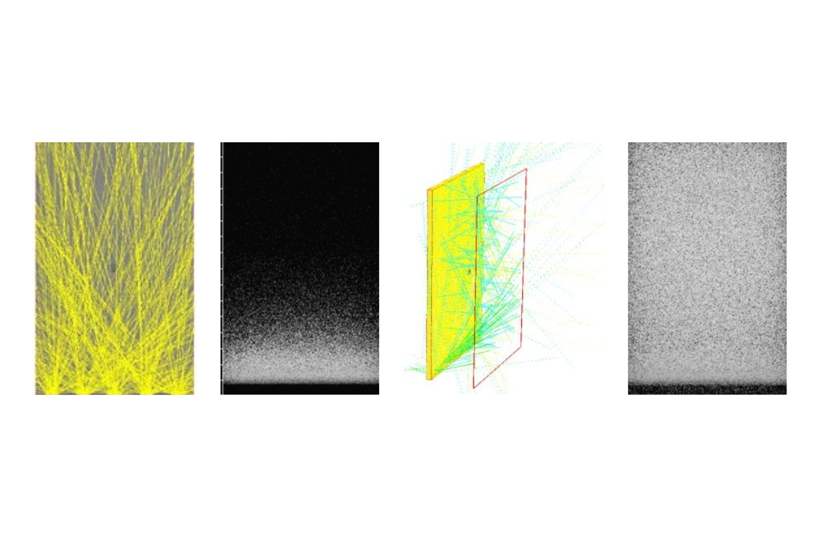
The irradiance exiting the mobile display, both before and after applying the scripted gradient diffuser, highlights the effectiveness of the diffuser. The logarithmic scaling of irradiance distribution provides a better understanding of what the human eye perceives.

Figure 6. Log(10) of irradiance distribution from mobile display without diffuser (left) and with exponential diffuser (right). Logarithmic scaling gives a better idea of what the human eye perceives. 250,000 rays were traced in this simulation.
Conclusion
The FRED model demonstrates that using a gradient diffuser in an edge-lit LED smartphone display significantly enhances uniform illumination and optical efficiency. By incorporating tailored scattering functions and reflective surfaces, mobile displays can achieve the desired performance while maintaining energy efficiency.
____________________________________________________________________________________________________________________________________________________________________________________
This blog post was created based on the information provided by Photon Engineering, a partner of CBS Europe.
Download the PDF: FRED Application - Edge-Lit LED Screen with Diffuser